- Installing a Back Half
Please read these instructions completely before starting any work.
1) Start by removing the fuel tank, gas lines, rear bumper, interior, and anything flammable or might get in the way during
the construction.
2) Set your car up on jack stands. Make sure to have the car up high enough to be able to get the back half in the car but
down low enough to keep the car stable. Place jack stands under the front and rear of the front clip and under the rear
part of the rocker panel. You will also need to support the back part of the body to keep it in place.
3) Level the car from side to side and front to back. Check this several times during the construction.
4) Mark the centerline of the rear axle on both sides of the car. Do this on the floor and on the side of the car by using a
piece of tape on the outside of the fender. Make sure the existing axle is in the car square before marking the centerline.
Now you can remove the rear end and all the old suspension.
5) Set up the new back half next to the car the way you will be installing it in the car.
6) On the new back half measure the distance from the center of the rear end to the front of the front cross member.
Transfer this dimension to your car and mark this on the floorboard. This is where you will cut the floorboard to install the
new back half. When cutting out the floorboard and trunk floor leave as much structure as possible to support the body
until the back half is fully installed.
7) Measure between your rocker panels at the point where the cross member will weld to it. (If the rocker panels are thin
or rusty you will want to plate this area with steel.) Trim the front cross member on the back to the dimension you measured.
When cutting the cross member make sure to keep the rear frame section in the center of the cross member.
8) Measure from where you will install the front cross member back to where you want the rear of the back half to connect
to the rear valance panel / bumper mounts. Trim the rear part of the frame rails to this dimension.
9) You are now ready to put the back half up into the car. Locate the cross member in the rocker panels at the height you
are planning on installing. Remember the higher up on the rocker panel you place the back half the lower the car will sit.
Support the cross member with jack stands. Move the rear of the back half in to place and support.
10) Level the cross member and double check to make sure the rest of the car is still level. Square the back half up in
the car using the dimension you measure from the centerline of the rear axle to the front of the cross member.
11) You are now ready to tack the back half in and check all your dimensions, and check if everything is square and
level.
12) When the back half is tack welded in securely install you rear suspension to make sure the center of your brackets
align with you centerline marks on the floor and fenders. Look over the body of the car and make sure it has not moved
and caused bulges or creases. Look at the door lines to see if they still line up good. Look at the truck lid to make sure it
still lines up good.
13) If everything checks out you are ready to weld the back half in the car.
14) Now you are ready to install your sub frame connectors, roll cage and remove the rest of the floor and trunk pan.
- Installing a Sway Bar on Checkered Racing Front End
1. Measure 6 ¼” from the control arm housing on either side toward the front of the rail. This will mark where the back of the sway bar frame mount bracket will sit(Rectangle bracket with two holes).
2. Once you have the location marked, place the rear of the bracket in line with that mark and tack weld it into place. The long side of the frame bracket should run parallel with the frame rail.
3. Now that the bracket is tacked into place you can now place your triangle gusset between the frame rail and top of the frame mount bracket. It should be in the center of the frame mount bracket. Make sure that the frame mount bracket is level before you finish weld the bracket and the gusset.
4. Repeat steps 1-3 on the opposite side.
5. Now that both frame mount brackets have been installed you can now move onto welding in the control arm sway bar mounts. (If you have our later model control arms with the plate, then skip steps 6 & 7)
6. With the lower control arms bolted onto the front end take one of the control arm mount brackets and place it between the lower shock mount bar and control arm tube toward the front of the front end. The bracket should be on the side of the lower shock mount bar that is toward the center of the front end.
7. Do the same on the opposite side control arm.
8. Now you can remove the sway bar hardware and begin to install the sway bar.
9. Take the sway bar end links and slide on one washer and one bushing with the bump on the bushing facing down and with the washer cupping the bushing.
10. Slide the end link down through the top of the sway bar mounting hole.
11. Do the same thing on the bottom side of the sway bar mounting hole. Bushing on first with the bump up towards the hole and one washer cupping the bushing.
12. Slide the long spacer onto the end link and repeat the same process with the washers and bushings on the control arm mounting tab and finger tighten the nut on the bottom of the tab.
13. Repeat this process for the other side.
14. Pull the sway bar forward and place a 1” buffer between the coil overs and sway bar end links.
15. Put the bolts through the sway bar bushings and the frame mounting tabs.
16. Completely tighten the nuts on the frame mounting tabs first and then the two nuts on the control arm mounting tabs.
17. Remove the 1” buffer and your sway bar is installed.
- Installation Instructions for Tube Front-End for 1962-1967 Chevy Nova.
1) Begin your installation by jacking the car up and supporting it on sturdy jack stands. The stands must be located on
the main car, just behind the firewall. Remember you are removing the front sub-frame so do not support the car under
the front sub-frame.
2) Start dismantling the front end. Start by removing the front wheels, front bumper and brackets. Disconnect the wiring
harness to the front components (IE: headlights, turn signals, parking lights). Next, remove the front fenders and grill.
Remove the core support, radiator, motor and transmission.
3) Now you are ready to unbolt the front sub-frame with the inner fenders. Support the front sub-frame with a floor jack
so it can be lowered to the ground safely.
4) Save all the nuts and bolts you have removed, they will be used to reassemble the car. Be sure to inspect all the nuts
and bolts, replace any that are damaged.
5) Remove the old steering box and steering column. The existing steering column can be used with the new rack and
pinion with some modifications.
6) While everything is out of the way, makes it a goodtime to clean the firewall up.
7) Raise the new sub-frame into place using a floor jack. After you have it in place and the bolt holes line up bolt it to the
car using the original nut, bolts and lock washers.
8) Bolt the upper firewall plates to the firewall.
9) Put the core support in place on the front of the frame and secure it using a pair of “C” clamps. Bolt the front Fenders
to the firewall and core support. Install the front bumper and brackets.
10) Check the core support to see if it is straight up and down. Now check the along the fenders and doors. Also, check
the alignment of the bumper and fenders. You can adjust the alignment by using a floor jack under the new sub-frame.
11) Once everything is lined up, trim the stabilizer bars to run from the upper firewall plates to just behind the core support
and weld in to place. Now drill a hole through the core support and into the new frame and bolt it together with a 3/8”
bolts and nuts.
12) Now you can install the motor and transmission. Before lowering the motor into the car, bolt your new motor mounts,
towers and headers to the motor. Hook the transmission mount up the existing cross member. Trim the towers to get
your motor to the desired height and position. Check all clearances. Weld the tower in to place. You might want to remove
the motor to do this.
13) If you are planning to use the existing column use a saws all or band saw the cut the column off right next to the
steering box. After you have separated the column from the steering box, trim an extra 1” off the outer column. Install the
column in the car.
14) Install the splined steering joint on to the rack and the smooth joint on to the column. Measure between the two
joints. Remember to allow for the steering shaft to slide all the way into the joint. Trim your shaft and install.
15) You are now ready to completely reassemble the car.
16) Once the car is setting back on the ground, adjust the coil-overs to 9.75”-10.50”. This is measured from center of
top shock bolt to center of bottom shock bolt. Take it to an alignment shop and have them set the front end:
Caster: 3 Degrees Positive
Camber: 0 deg
- Installing a 67-69 Camaro/ 68-74 Nova Front End
1) Begin your installation by jacking the car up and supporting it on sturdy jack stands. The stands must be located
on the main body. Remember you are removing the front sub-frame so do not support the car under the front sub-frame.
2) Start dismantling the front end. Start by removing the front wheels, front bumper and brackets. Disconnect the
wiring harness to the front components (IE: headlights, turn signals, parking lights). Next, remove the front fenders and
grill. Remove the core support, radiator, motor and transmission.
3) Now you are ready to unbolt the front sub-frame. Support the front sub-frame with a floor jack so it can be
lowered to the ground safely.
4) Save all the nuts and bolts you have removed, they will be used to reassemble the car. Be sure to inspect all the
nuts and bolts, replace any that are damaged.
5) Remove the old steering box and steering column. The existing steering column can be used with the new rack
and pinion with some modifications.
6) While everything is removed, this is a goodtime to clean the firewall up.
7) Raise the new sub-frame into place using a floor jack. After you have it in place and the bolt holes line up then
you can put the solid body bushings in place and bolt it to the car using the original nut, bolts and lock
washers.(aftermarket
or stock bushings can be used with modifications to body mounts.)
8) Put the core support in place on the front of the frame and secure it using a pair of “C” clamps. Bolt the front
Fenders to the firewall and core support. Install the front bumper and brackets.
9) Check the core support to see if it is straight up and down. Now check the along the fenders and doors. Also,
check the alignment of the bumper and fenders. You can adjust the alignment by using a floor jack under the new subframe.
10) Now you can install the motor and transmission. Before lowering the motor into the car, bolt your new motor
mounts, towers and headers to the motor. Mock up the transmission cross member into desired location then weld or bolt
into place. Trim the towers to get your motor to the desired height and position. Check all clearances. Weld the tower in
to
place. You might want to re- move the motor to do this.
11) If you are planning to use the existing column use a sawzall or band saw the cut the column off right next to the
steering box. After you have separated the column from the steering box, trim an extra 1” off the outer column. Install the
column in the car.
12) Install the splined steering joint on to the rack and the smooth joint on to the column. Measure between the two
joints. Remember to allow for the steering shaft to slide all the way into the joint. Trim your shaft and install.
13) You are now ready to completely reassemble the car.
14) Once the car is setting back on the ground, adjust the coil-overs to between 9.75”-10.50”. This is measured from
center of top shock bolt to center of bottom shock bolt. Take it to an alignment shop and have them set the front
end:
Caster: 3 Degrees Positive
Camber: 0 degrees Positive
Tow: 1/8” in.
- Installing a 70-81 Camaro
1) Begin your installation by jacking the car up and supporting it on sturdy jack stands. The stands must be located on
the main body. Remember you are removing the front sub-frame so do not support the car under the front sub-frame.
2) Start dismantling the front end. Start by removing the front wheels, front bumper and brackets. Disconnect the
wiring harness to the front components (IE: headlights, turn signals, parking lights). Next, remove the front fenders and
grill. Remove the core support, radiator, motor and transmission.
3) Now you are ready to unbolt the front sub-frame. Support the front sub-frame with a floor jack so it can be lowered
to the ground safely.
4) Save all the nuts and bolts you have removed, they will be used to reassemble the car. Be sure to inspect all the nuts
and bolts, replace any that are damaged.
5) Remove the old steering box and steering column. The existing steering column can be used with the new rack and
pinion with some modifications.
6) While everything is removed, this is a goodtime to clean the firewall up.
7) Raise the new sub-frame into place using a floor jack. After you have it in place and the bolt holes line up then you
can put the solid body bushings in place and bolt it to the car using the original nut, bolts and lock washers.(aftermarket
or stock bushings can be used with modifications to body mounts.)
8) Put the core support in place on the front of the frame and secure it using a pair of “C” clamps. Bolt the front Fenders
to the firewall and core support. Install the front bumper and brackets.
9) Check the core support to see if it is straight up and down. Now check the along the fenders and doors. Also, check
the alignment of the bumper and fenders. You can adjust the alignment by using a floor jack under the new sub-frame.
10) Now you can install the motor and transmission. Before lowering the motor into the car, bolt your new motor
mounts, towers and headers to the motor. Mock up the transmission cross member into desired location then weld or
bolt into place. Trim the towers to get your motor to the desired height and position. Check all clearances. Weld the
tower in to place. You might want to re- move the motor to do this.
11) If you are planning to use the existing column use a sawzall or band saw the cut the column off right next to the
steering box. After you have separated the column from the steering box, trim an extra 1” off the outer column. Install
the column in the car.
12) Install the splined steering joint on to the rack and the smooth joint on to the column. Measure between the two
joints. Remember to allow for the steering shaft to slide all the way into the joint. Trim your shaft and install.
13) You are now ready to completely reassemble the car.
14) Once the car is setting back on the ground, adjust the coil-overs to between 9.75”-10.50”. This is measured from
center of top shock bolt to center of bottom shock bolt. Take it to an alignment shop and have them set the front end:
Caster: 3 Degrees Positive
Camber: 0 degrees Positive Tow: 1/8” in.
- Instructions for Tri-5 Weld-on front end
A qualified professional welder or fabricator with the technical
understanding of product function and installation procedures
must install this product. After installation, front end alignment
is required.
Start by removing the doghouse and placing the vehicle on jack stands. Be sure to level all four corners
of your vehicle and thoroughly inspect your frame for any kinks or damage.
Once this is done you are ready to begin. Measure from the center of your front wheel to the front of
the door and mark this measurement down, as it will be helpful later. Also, measure from the top of
your core support crossmember to the floor to help with setting the height of your new front clip later.
Next, be sure to measure your wheel base as it should come out to be 115” no matter the year or model
of your vehicle. Throughout this process verify that your vehicle remains level.
On your new Checkered Racing front end take a measurement from the front of the rail to the front of
the block on the rear. Transfer this measurement to your existing frame as this will mark your cut point.
Mark this point by drawing a line completely around the frame.
Before you begin cutting tack weld a frame support just beyond your cut marks. This will help your
frame to stay stable as you remove the front clip.
Once the frame support is in place be sure to support the front frame section with a pair of jack stands.
You are now ready to begin cutting. It makes it much easier to start with the bottom and sides leaving
the top portion of the rail for last. A reciprocating saw, plasma cutter or cut off wheel can be used for
this step.
Now that the front clip is removed be sure to clean the stubs of any rust, burs or imperfections that
might impact your welding later.
For proper fit the frame must be cut and split so that the new clip can slide into the existing frame. Once
cut the factory rails can be squeezed around the new clip to fully mate and support it.
Now it is time to test fit your new front clip. Start by setting your new clip on jack stands to the height
you previously measured from your original core support crossmember. Be sure to verify this
measurement and that the clip is positioned square.
Once your clip is set at the correct height measure from the center of the spindle to the front of the
door and compare with the measurement taken from the original frame.
Once that is done you are now ready to clamp everything in place. Before welding be sure to double
check the measurements you have taken previously and make sure your front clip is still level.
From there you should check to make sure your wheelbase comes out be 115”. Be sure to measure this
on both sides of your frame.
After verifying you have the correct wheelbase set you should then measure from left rear axle to right
front axle and right rear to left front. These two measurements should be the exact same and will insure
your front clip is square.
Once the front clip is tack welded into place check the previous measurements once again before
moving to the next step.
You can now set the doghouse back onto the frame. The core support will sit on the crossmember and
with no shims in place the front nose should have a slight downward tilt.
Place your wheels on the front clip and check to see that everything is lined up correctly.
If everything is lined up and square you can then remove the doghouse to make finish welding easier.
Then squeeze the outer and top portions of the frame with clamps to mate the two frames. Start by
welding the inside rails to the inside of the factory rails and along the bottom. Do not start at the top or
outsides.
When finished welding you can then removed the temporary support that was placed in the beginning.
The motor mount crossmember will need to be cut down to fit and mock up the engine. With the
distributor installed be sure there are no clearance issues. This is also a good time to test fit headers and
steering.
Once clearance issues are addressed you can then fully weld in your engine crossmember/ frame motor
mounts and connect your steering linkage.
Alignment Specs:
0 Degrees Caster
3 Degrees positive camber
1/8” tow in
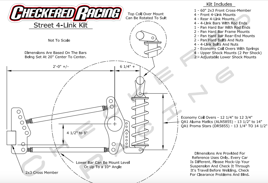
- 4 Link Install Tips
- Installation Guidelines for Ladder Bar Kits
1. Start by taking one of the ladder bars and mocking it up against the rear end to find the best location for mounting. Our ladder bars are meant to be used with coil over shocks only, so all existing rear end shock and leaf spring brackets should be removed.
2. It is recommended that our ST AND ARD ladder bars be mounted at 24" center to center but also mounted as to cause no interference with other components.
3. Ladder bars should be mounted on either side of the rear end equally from the housing ends.
4. Once the location is determined we recommend that the brackets be tack welded to continue the mock up process.
5. Start with the bottom bar of the ladder bars as close to level as possible with around 3 degrees of downward pinion angle.
6. Now is also a good time to mock up the coil over shocks and the diagonal link bar so that all components can be checked through travel together. Diagonal link bars are sent for ladder bars set at 24" center to center but can be cut down if needed.
7. Now that the rear brackets are tacked into placed you can continue the mock up process by finding the best location for the front cross member.
8. Our round tube front cross members also come long and are meant to be cut to fit. It is best to weld the cross member in between any existing frame rails or subframe rails if possible.
9. Floor pan and/ or trunk pan may be necessary in order to mount the bars and cross member. Be sure to check the suspension travel throughout this process.
- Installation Instructions for 63-72 C10 IFS
1. These instructions assume the existing crossmember, suspension, etc. is
removed from the frame before beginning to install this front end.
2. This job is made easiest by engine and dog house being removed before
you begin.
3. Once you have everything removed, make sure that the frame is level and
sturdy, preferably on jack stands.
4. From there you can slide the new Checkered Racing front assembly under
the frame and begin to align the mounting holes. This job might be made
easier by removing the control arms, shocks and any other components
that might get in your way.
5. Before you begin to bolt the assembly to your frame please note that you
will need to drill out the existing mounting holes on your frame to ½”.
6. You can begin by bolting the IFS to your frame using the existing holes and
provided hardware.
7. Once the front end is firmly mounted you can begin to drill the remaining
two ½” holes on each side using the bracket as a template.
8. Now that the front end is completely mounted to you frame go ahead and
mount all the components back to the assembly if you chose to remove
them.
9. Please note it is required the shock be completely extended with no
pressure on the spring before you add the brakes and spindles.
10. Once you have the control arms, shocks and rack mounted you can add the
brakes and spindles.
11.After you have placed the brake and spindle assembly over the ball joint, it
is necessary that you use the provided spacers to align the cotter key.
Generally one thick spacer is used on the bottom and one thin spacer for
the top(Each Side).
12.Once the brakes and spindles are mounted you can now re-tighten the
springs. This is made easiest by available thrust bearing and spanner
wrench kit but can also be done with channel locks. For best ride be sure
shock is adjusted between 12”-12 ½” from center of top eyelet to center of
bottom eyelet.
13.From here you can begin to mock up your steering and engine. A second ujoint
will be required to connect to your steering column. A tab mounted on
the frame and included rod end are to be used as a steering shaft stabilizer
if necessary.
14.It is recommended that you have this front end aligned properly before
being driven.
If you have any further questions or concerns please contact Checkered Racing at
812-606-7223
Alignment Specs
Caster- 3 Degrees Positive
Camber- 0 Degrees
Tow In- 1/8”
- BREAK–IN INFORMATION
NEW GEAR BREAK-IN
All new gear sets require a break-in period to prevent damage from overheating. After driving the first 15 to 20 miles it is best to stop and let the differential cool before proceeding. RRP’S warranty requires at least 500 miles before towing. RRP also requires towing for very short distances (less than 15 miles) and letting the differential cool before continuing during the first 45 towing miles. This may seem unnecessary but it is very easy to damage the differential by loading it before the gear set is completely broken in. RRP recommends changing the oil after the first 500 miles. This will remove any metal particles or phosphorus coating that has come from the new gear set.
The greatest damage results when a new ring & pinion has been run for serveral miles during the first 500 miles and the oil is very hot. Any heavy use or overloading at this time will cause irreparable damage to the gear set that can be determined by inspection of the gear set and will not be warranted by RRP.
ANY OVERLOADING OR OVERHEATING WILL CAUSE THE GEAR OIL TO BREAK DOWN AND THE RING & PINION WILL FAIL.
OIL LEVEL
Many differentials are easy to fill with gear oil. However, the 9” Ford design can be difficult to fill completely. The location of the fill plug on the 9” Ford can cause oil to run back out before it is completely full. Most 9” housings hold at least 3 quarts of oil and sometimes as much as 5 quarts. It is important to take your time and be sure that the oil has settled into all of the crevices and recheck the oil level to be certain that it is completely full before driving the vehicle.
SIGNS OF LUBRICATION FAILURE
When a gear runs low on oil, damage is sure to result. The cause of damage is not always obvious. When a differential runs low on oil, the oil volume may not be sufficient to keep the gear cool. Once the oil breaks down from contact with the hot gear, wear occurs very rapidly. Material will war off of the drive side of both the ring & pinion teeth and leave a feather like pattern on both surfaces. A gear that wears from friction due to lack of lubrication and excessive heat seldom experiences a color change from heat because any discoloration is worn off of the teeth during each contact.
Ring gears and pinion gears are heat treated separately so that the pinion, whose teeth make contact more often than the ring gear, is designed to be harder. To accomplish this the two gears are heat treated separately and a soft gear will not cause both the ring & pinion to wear.
WARRANTY INFORMATION
WARRANTY EXCLUSIONS
Any damage due to abuse, overloading, or lubrication failure (e.g. oil deterioration, water contamination, low oil level). Any vehicles used off road or for completion. The following vehicles will not be warranted due to the overloading caused by tall tires. Mini and mid-sized vehicles with tires over 31” tall. Full size ½ ton vehicles with tires over 33” tall. Full size ¾ or 1 ton vehicles with tires over 35” tall.
ALL ITEMS ARE WARRANTED BY THEIR RESPECTIVE MANUFACTURERS, BUT NOT BY RRP.
All rebuilt items are warranted for 3 months against defects in materials and workmanship, not against abuse, overloading, or improper lubrication. All parts must be returned to our shop freight prepaid for our inspection and determination. We do not authorize and will not pay for outside repairs. ANY UNAUTHORIZED OUTSIDE REPAIRS VOID THIS WARRANTY. We will not pay for; inconvenience, loss of time or revenue, telephone calls, commercial losses, or loss of perishable goods. This is our only warranty expressed or implied. All returned goods must be accompanied by this bill within 30 days and will be charged a 10% service charge for handling.
POSITRACTIONS
Positraction chatter is normal for limited slip and positraction differentials. Both rear tires must measure the same height from the ground to the top of the wheel in order for the differential to function properly without premature wear. Limited slip additive or friction modifier for limited slip differentials must be used with the oil to reduce positraction chatter in the event that the oil is changed.
LOCKERS
Mechanical Locking differentials will bang and clunk during normal operation. Both rear tires must measure the same height from the ground to the top of the wheel in order for a locking differential to function properly.
GEAR NOISE
Richmond Gear and other aftermarket (non OEM) gears are designed primarily for strength and may be noisy. This noise is especially inherent in vans and quiet passenger cars.
We hope this information prevents you from running into trouble. We sincerely appreciate your business. In the future, if we can be of service to you, or any of your friends, please give us a call or stop by.


ABOUT US
From street rods to racecars, Checkered Racing is your suspension connection. We fabricate and sell a complete line of back half and front ends to fit your needs. Our back halfs are available in any width you need to fit your project. You can order them in any stage of completion with whatever options you would like.
Shop Hours
Monday - Friday7:30 am — 4:30 pm
SALES/TECH HOURS
Monday - Saturday7:30
am — 4:30 pm